
After fiber optic cables are installed and laid, it is time to test them. This activity should be performed on each fiber optic cable installation to check for continuity, loss, and power. We need the right tools to perform such measures. An optical power meter is the first.
What is an optical power meter
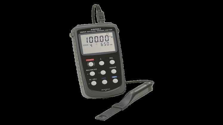
Optic power meters (or OPMs) are devices that measure the power of an optical signal. Usually, the term refers to devices that test average power in fiber optics systems.
An optical power meter typically consists of a calibration sensor, a measurement amplifier, and a display. The sensor is basically a photodiode that has been selected to provide the correct range of wavelengths and power level. Photodiode definition is the base knowledge that optical power meter designers should know, becouse sensors are the main part of best devices of that type. The display displays the measured optical power as well as the wavelength. The calibration standards used to calibrate the meters include NIST.
An optical power meter is able to detect a wide range of light. However, calibration depends on wavelength. Although this is not usually a problem, the test wavelength is known. However, it does have some disadvantages. The first is that the user must set the meter at the correct wavelength. Second, any interfering waves can cause erroneous readings.
How do you use an optical power meter?
We can now measure the optical power of the transmitter after calibrating it. We need to calibrate the optical power meter to get the correct range (usually dBm but sometimes mW) as well as the wavelength for measuring power. Once everything is set up, you can connect the optical powermeter to the receiver to measure its power or to the test-cable that is connected to system source to measure transmitter power. Next, we need to mark the value and compare it against the system’s power.
We can also calculate optical loss using an optical power meter. We connect the fiber optic cable to an optical transmission device via a fiber optic pipe and measure its signal power. Next, we measure the length of the fiber optic cable. The total optical loss is the difference between these measurements. Add all losses at different sections to get the total loss on the signal.
How do you choose the best optical power meter?
An optical power meter is essential for the testing of optical fibers. It is important to select the right device. Consider the wavelength calibration, interface type, and measurement range when shopping for a device.
Let’s first analyze the application. An optical power meter is able to measure the absolute optical power of a fiber optic link or fiber optic device. There are also meters for specific applications such as the PON and CWDM optical powers meters. These meters can be used to quickly and easily measure power for each application.
Each optical power meter can handle a specific wavelength range, usually between 800 and 1700 nm. It is recommended that the optical power meter be calibrated to the same wavelengths as the equipment in order to obtain a more precise value. The most common wavelengths are 850nm (1310nm) and 1550nm (1550nm). It is important to remember both the wavelength range supported and its calibration.
A measurement range refers to a fraction of the optical power a device can measure. The optical power that optical power meters are capable of measuring ranges between -70 and +30 dBm.
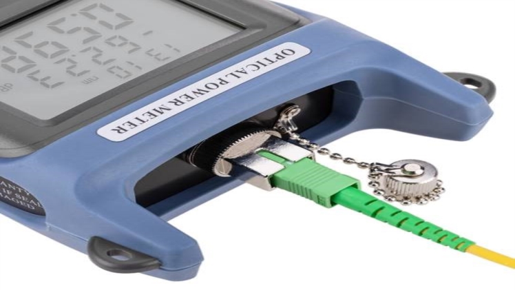
A length of fiber optic cable is used to connect an optical power meter port to the appropriate port on fiber-optic testing equipment. It is possible to fix optical connectors on optical power meters. Many optical power meters have one FC adapter. There are many options for interchangeable adapters available on the market for optical power meters that don’t require a lot of connecting cables.
An optical power meter can be a simple tool for testing fiber optics. It can significantly increase technician productivity.