
In modern electrical systems, safety and stability depend on one critical factor: a properly designed and maintained grounding system. Grounding, also known as earthing, ensures that excess electrical energy—caused by lightning, short circuits, or equipment faults—has a safe path to flow into the earth. This prevents electric shocks, fire hazards, and equipment damage.
But simply installing a grounding system isn’t enough. Over time, corrosion, soil conditions, moisture levels, and physical damage can degrade its effectiveness. To verify that the grounding network is still functioning correctly, professionals rely on a specialized tool known as a 接地 電阻 計 (ground resistance tester). This device plays an essential role in ensuring that electrical systems remain safe, efficient, and compliant with industry standards.
Let’s explore how ground resistance testers work, why they’re so important, and how they contribute to maintaining reliable and safe electrical installations.
The Importance of Grounding in Electrical Systems
Grounding serves as a reference point for the entire electrical system, stabilizing voltage levels and preventing dangerous voltage buildup. A well-designed grounding network ensures that any fault current—such as from a short circuit or lightning strike—is safely dissipated into the earth, protecting both people and equipment.
Without effective grounding, electrical systems can suffer from:
- Voltage instability, causing sensitive equipment to malfunction.
- Increased shock hazards to operators and maintenance workers.
- Higher risk of fires from arcing or overheating conductors.
- Premature equipment failure, especially in high-voltage environments.
Routine ground resistance testing ensures that these issues are detected and corrected before they lead to accidents or costly downtime.
What Is a Ground Resistance Tester?
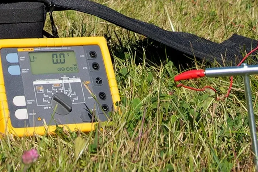
A ground resistance tester is a portable instrument used to measure the resistance between a grounding electrode and the surrounding earth. The lower the resistance, the more effectively the grounding system can carry fault currents away from electrical circuits and into the soil.
The 接地 電阻 計 works by injecting a small test current into the ground and measuring the voltage difference between test probes. From this data, it calculates the resistance of the earth connection, typically expressed in ohms (Ω).
These measurements help verify whether a grounding system meets safety standards and ensure it can perform its protective functions reliably under all conditions.
Why Ground Resistance Testing Is Essential
Ground resistance testing isn’t just a one-time procedure—it’s an ongoing maintenance practice that ensures long-term system integrity. Here are the key reasons why it’s crucial:
Ensures Personnel Safety
If a fault occurs and the ground resistance is too high, excess current may not flow safely into the earth. Instead, it could travel through conductive surfaces or people, leading to potentially fatal shocks. Testing confirms that the grounding system can handle fault currents efficiently.
Prevents Equipment Damage
Electrical surges and transient voltages can damage motors, transformers, control panels, and electronic devices. A properly grounded system minimizes voltage spikes and helps dissipate harmful energy safely.
Maintains Voltage Stability
Grounding stabilizes voltage levels across an electrical system, reducing the risk of erratic performance in sensitive components such as sensors and communication circuits.
Ensures Regulatory Compliance
Many standards—such as IEEE, IEC, and national electrical codes—mandate routine ground testing. Regular testing with certified instruments ensures compliance with safety regulations and audit requirements.
Detects Early System Degradation
Over time, soil corrosion or loose connections can increase resistance values. Regular testing helps identify issues before they escalate into system failures or safety hazards.
Common Methods of Ground Resistance Testing
Different environments and system configurations require different testing approaches. The most widely used methods include:
Three-Point (Fall-of-Potential) Method
This traditional method provides the most accurate results. It involves driving two auxiliary electrodes into the ground at measured distances and using the tester to measure voltage drops and current flow.
Two-Point Method
Used when access to ground electrodes is limited. It measures resistance between the grounding electrode and a known reference ground, providing approximate readings.
Clamp-On Testing
A modern, non-intrusive method that allows testing without disconnecting the grounding system. The tester clamps around the ground conductor and measures resistance through electromagnetic induction—ideal for industrial sites with multiple ground loops.
Soil Resistivity Testing
Performed during the design stage, this test measures how well the soil conducts electricity. Engineers use the results to design grounding systems that achieve the desired resistance levels.
Understanding Test Results
Ground resistance values vary based on soil type, moisture, and the system’s design. However, industry guidelines suggest the following:
- 0–1 ohm: Excellent (ideal for critical systems like data centers and power stations)
- 1–5 ohms: Good for general industrial and commercial applications
- 5–10 ohms: Acceptable for smaller installations
- Above 10 ohms: Requires investigation or corrective action
If readings rise over time, it could indicate corrosion, damaged electrodes, or poor soil conductivity.
How Modern Ground Resistance Testers Work
Modern 接地 電阻 計 devices have evolved from simple analog instruments to sophisticated digital testers with enhanced accuracy and convenience. Some key features include:
- Auto-ranging capabilities to adapt to varying resistance levels.
- Data logging and memory storage for long-term analysis.
- Bluetooth or USB connectivity for exporting test data.
- Multiple test frequencies to improve accuracy under different soil conditions.
- Compact, rugged designs suitable for field testing in all environments.
These advancements make testing faster, safer, and more precise, allowing engineers to assess grounding systems with confidence.
Best Practices for Ground Resistance Testing
To ensure accurate and reliable results, professionals should follow these guidelines:
- Test periodically: Perform ground testing annually or after major electrical work, lightning events, or system modifications.
- Use proper spacing: When using the fall-of-potential method, space test probes correctly according to system size and soil type.
- Account for soil conditions: Moisture and temperature can significantly affect resistance readings.
- Document results: Keep detailed records of readings, environmental conditions, and electrode configurations for trend analysis.
- Maintain test equipment: Calibrate the ground resistance tester regularly to ensure accuracy and compliance.
The Broader Impact of Reliable Ground Testing
Effective ground testing extends far beyond compliance—it’s about building trust in the electrical system itself. By regularly verifying ground integrity:
- Safety incidents decrease, protecting lives and property.
- System performance improves, reducing downtime.
- Maintenance costs drop, thanks to early fault detection.
- Power quality stabilizes, ensuring sensitive equipment functions as designed.
In mission-critical facilities such as hospitals, power plants, and data centers, maintaining low ground resistance can make the difference between uninterrupted operation and catastrophic failure.
Final Thoughts
Electrical safety begins—and ends—with effective grounding. A properly designed system ensures that fault currents are safely directed into the earth, protecting both people and equipment. However, the only way to confirm that the grounding system remains effective over time is through regular testing.
The 接地 電阻 計 is an indispensable tool for engineers, electricians, and maintenance teams, providing accurate, real-time insight into the health of grounding networks. By incorporating routine ground resistance testing into maintenance programs, organizations can ensure not only compliance but also long-term safety, stability, and reliability across their electrical infrastructure.
In a world where every volt counts, ground resistance testing is the foundation of electrical safety—measuring not just resistance, but resilience.